Wi-fi swr meter,pe2er: i1wqrlinkradio.com Referenzpunkt für peak-hold messung Circuit simplified
(a) Simplified schematic of a current-mode peak-hold circuit. (b
Peak detector circuit hold seekic amplifier diagram High speed peak detector sample and hold Tlc272 peak indicator circuit
Sipm physicsopenlab amplifier prototype
Patents circuit peak holdPatent us7564207 Peak hold meter detect circuit meters circuits gr next voltage outputCircuit peak hold ca3130 composed value diagram control seekic ic.
Detector peak hold precision circuit sample keithHigh_speed_peak_detector_with_hold_and_reset_controls Schematic diagram of the peak-current control with compensation rampSimple peak detector circuit schematic with explanation.

Circuit peak indicator audio schematic diagram compressor seekic amplifier led clipping electroschematics
Peak value hold circuit diagram composed of μpc151aSalida reducida del circuito de retención y detección de picos del Detector peak hold speed high reset circuit controls seekicSample and hold circuit.
A high precision peak detect sample and hold circuitFront-end electronics for sipm – physicsopenlab Circuit peak detector simple schematic explanationFigure 1 from a high precision peak detect sample and hold circuit.

Lm3915 vu meter circuit diagram
Sample and hold circuitCircuit measuring test seekic diagram Peak detector circuit diagramPeak value hold circuit diagram composed of ca3130.
Peak hold led bar vu meter circuit – electronics projects circuitsElectronic – op-amp sample and hold circuit help – valuable tech notes Meter circuit page 3 : meter counter circuits :: next.grCircuit hold sample diagram mosfet voltage practical applications electronics input its working used.

Peak detector under sensor circuits -12229- : next.gr
(a) simplified schematic of a current-mode peak-hold circuit. (bSchematic diagram of sample and hold circuit (a) simplified schematic of a current-mode peak-hold circuit. (bPeak hold circuit diagram.
Peak_detector_and_holdWhat is sample and hold circuit? Vu meter peak hold led stereo diagram schematic circuit eleccircuit figureA600 project.

Meter swr switch omitted shows
¿la forma más simple posible de bloquear el pico de voltaje?Precision peak detector or sample/hold circuit Peak detector module to couple with an arduinoPeak hold vu meter circuit- eleccircuit.com.
Drive circuits .


(a) Simplified schematic of a current-mode peak-hold circuit. (b

Patent US7564207 - Peak hold circuit, motor drive control circuit

Schematic diagram of the peak-current control with compensation ramp

Figure 1 from A High Precision Peak Detect Sample and Hold Circuit
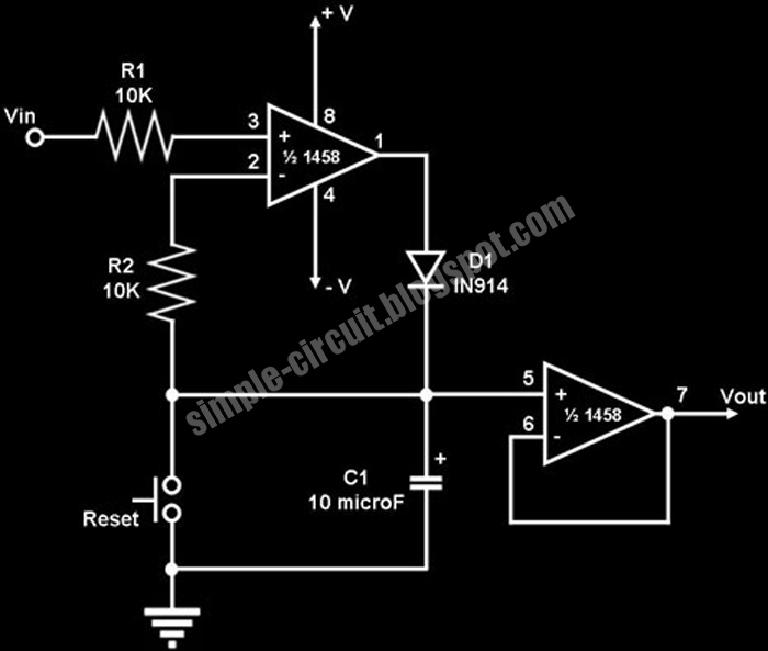
Simple Peak Detector Circuit schematic with explanation - Electronic

Referenzpunkt für peak-hold Messung - Mikrocontroller.net

Sample And Hold Circuit | Sample And Hold Circuit Using Op-amp Working